Current Limiting Resistor Calculator for Leds
-
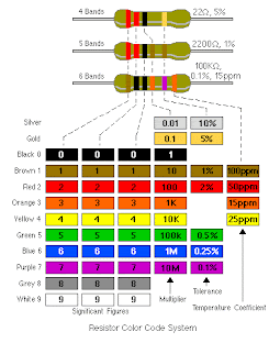
If you want to calculate Resistor, please visit Here!
Some good values to try:
As supply voltage:
For molex: 5, 7 and 12 volts
Batteries: 1.5 and 9 volts
...
5:30 PM
If you want to calculate Resistor, please visit Here!
 Some good values to try:
As supply voltage:
For molex: 5, 7 and 12 volts
Batteries: 1.5 and 9 volts
As led forward voltages:
Red and green: 2 volts
Blue and white: 3.5 - 4 volts
Led current:
20mA will work for most regular leds.
Superbright leds can go from 30mA up to several amps.
Other CURRENT LIMITING RESISTOR CALCULATOR: FOR LIGHT EMITTING DIODES
The calculators on this page can be used to find current limiting resistors and currents for Light Emitting Diodes.
The first calculator determines the resistance for a desired LED current while the second calculates the current for a given resistance.
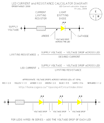 Voltages in Volts - Current in Milliamps - Resistance in Ohms
When selecting resistors - It is advisable to choose the next higher standard value.
A browser capable of running Javascript is required for this calculator.
If LED's are connected in series - ADD their voltage drops together to get the total voltage drop.
Entering a zero for the LED voltage drop will yield the resistance and wattage for a resistance only circuit.
Please Go here : Other CURRENT LIMITING RESISTOR CALCULATOR: FOR LIGHT EMITTING DIODES
8:23 PM
Here's a simple problem: "How do you make an LED turn on when it gets dark?"  You might call it the "nightlight problem," but the same sort of question comes up in a lot of familiar situations-- emergency lights, street lights, silly computer keyboard backlights, and the list goes on.
Solutions? Lots. The time-honored tradition is to use a circuit with a CdS photoresistor, sometimes called a photocell or LDR, for "light-dependent resistor." Photoresistors are reliable and cost about $1 each, but are going away because they contain cadmium, a toxic heavy metal whose use is increasingly regulated.
There are many other solutions as well. Look here for some op-amp based photodetector circuits with LED output, and check out some of the tricks used in well-designed solar garden lights, which include gems like using the solar cell itself as the sensor.
In this article we show how to build a very simple-- perhaps even the simplest-- darkness-activated LED circuit. To our LED and battery we add just three components, which cost less than thirty cents altogether (and much less if you buy in bulk). You can build it in less than five minutes or less (much less with practice)
What can you do with such an inexpensive light-controlled LED circuit? Almost anything really. But, one fun application is to make LED throwies that turn themselves off in the daytime to save power. Throwies normally can last up to two weeks. Adding a light-level switch like this can significantly extend their lifetime.

Here are our components: On top: a CR2032 lithium coin cell (3 V). On the bottom (L-R): the LED, an LTR-4206E phototransistor, a 2N3904 transistor, and a 1 k resistor. This LED is red, blindingly bright at 60 candela, in a 10 mm package. It casts a visible beam, visible for about twenty feet in a well-lit room. We got the LEDs and batteries on eBay, and the other parts are from Digi-Key, but Mouser has them as well. As we mentioned, the last three cost about $0.30 all together, and much less in bulk.
The LTR-4206E is a phototransistor in a 3mm black package. The black package blocks visible light, so it is only sensitive to infrared light-- it sees sunlight and incandescent lights, but not fluorescent or (most) discharge lamps-- it really will come on at night.
Our starting point is the simplest LED circuit: that of the LED throwie, which has an LED driven directly from a 3V lithium coin cell. From this, we add on the phototransistor, which senses the presence of light, and we use its output to control the transistor, which turns the LED on.

The circuit diagram looks like this; please ignore the messy handwriting. ;)
When light falls on the phototransistor, it begins to conduct up to about 1.5 mA, which pulls down the voltage at the lower side of the resistor by 1.5 V, turning off the transistor, which turns off the LED. When it's dark, the transistor is able to conduct about 15 mA through the LED. So, the circuit uses only about 1/10 as much current while the LED is off. One thing to note about this circuit: We're using a red LED. That's because the voltage drop across the transistor allows less than the full 3 V across the LED. The full three volts is really only marginal for driving blue LEDs anyway, so two-point-something really doesn't cut it. (Might be able to work around that with a cheap FET-- haven't tried yet.)
And now, let's build it. You can certainly put this together on a breadboard, but there's something more satisfying about the compact and deployable build that we walk through here.


First get the transistor and the resistor. The pins of the 2N3904 are called (left-to-right) Emitter, Base, Collector, when viewing it from the front such that you can read the writing. We're going to solder the resistor between the leads of the Base and Collector of the transistor. Unusual part: hold the resistor with its leads at 90 degrees to those of the transistor while you solder.
Read more
Stay safe when you do this.
After soldering, clip off the excess resistor lead that is attached to the transistor base (middle pin), as well as the excess length of the collector pin.

 Next, we add the phototransistor. Note that it has a flatted side, much like an LED does. This pin on that side is the collector of the phototransistor. Solder the collector (flatted side) to the middle pin (the base) of the transistor, again at 90 degrees. The other pin of the phototransistor, the emitter, is left unconnected for the moment. (Here is an alternate view of what that should look like when you're done.)
Finally, we need to add the LED. To do so, we need to know which side is the "positive," or anode side of the device. Regrettably markings of LEDs are not consistent, so the best way to be sure is to test it with the lithium coin cell-- put the LED across the terminals of the cell and, when it lights up, note which side is touching the (+) terminal. (Usually, it's the one with the longer lead.) Solder the "positive" lead of the LED to the emitter pin of the transistor-- it's the one on the left, which doesn't have anything soldered to it. Trim away the excess lead of the LED that goes past the solder joint. Solder the other pin of the LED (the "negative" pin, or cathode) to the emitter of the phototransistor, the pin on the non-flatted side, which does not have anything connected to it yet.
 By this point, there are only two pins sticking down below the components: One that goes to the resistor and collector (rightmost pin) of the transistor, and one that goes to the emitter of the phototransistor and to the cathode of the LED.

To test the circuit, squeeze the coin cell between these two terminals, positive side goes to the lead touching the resistor. You can't see the LED on here because these photos were taken with incandescent lighting-- it wouldn't turn on.

 Bending the leads to contact the lithium cell a little more reliably, you can try it out a little more easily. In the photo on the right, I cupped my hand over the circuit-- so the LED turned on.

 To make this into an actual "throwie," you still need to add some tape and a magnet, but that's quite easily done. This one makes a pretty good nightlight attached to the top of a doorframe-- when the room lights are off, it shines a bright, bright spot on the ceiling.
Where to go from here? While this little circuit can do something on its own, it would probably also be happy as part of a larger circuit. At a minimum, note that if you work with batteries that have lower internal resistance than the lithium coin cells, you should place an appropriate resistor in series with the battery before trying to operate this circuit-- or else you may put too much current through the LED. Certainly, this is one of the easiest and least expensive ways to control an LED with a photosensor.
 You might call it the "nightlight problem," but the same sort of question comes up in a lot of familiar situations-- emergency lights, street lights, silly computer keyboard backlights, and the list goes on.
Solutions? Lots. The time-honored tradition is to use a circuit with a CdS photoresistor, sometimes called a photocell or LDR, for "light-dependent resistor." Photoresistors are reliable and cost about $1 each, but are going away because they contain cadmium, a toxic heavy metal whose use is increasingly regulated.
There are many other solutions as well. Look here for some op-amp based photodetector circuits with LED output, and check out some of the tricks used in well-designed solar garden lights, which include gems like using the solar cell itself as the sensor.
In this article we show how to build a very simple-- perhaps even the simplest-- darkness-activated LED circuit. To our LED and battery we add just three components, which cost less than thirty cents altogether (and much less if you buy in bulk). You can build it in less than five minutes or less (much less with practice)
What can you do with such an inexpensive light-controlled LED circuit? Almost anything really. But, one fun application is to make LED throwies that turn themselves off in the daytime to save power. Throwies normally can last up to two weeks. Adding a light-level switch like this can significantly extend their lifetime.

Here are our components: On top: a CR2032 lithium coin cell (3 V). On the bottom (L-R): the LED, an LTR-4206E phototransistor, a 2N3904 transistor, and a 1 k resistor. This LED is red, blindingly bright at 60 candela, in a 10 mm package. It casts a visible beam, visible for about twenty feet in a well-lit room. We got the LEDs and batteries on eBay, and the other parts are from Digi-Key, but Mouser has them as well. As we mentioned, the last three cost about $0.30 all together, and much less in bulk.
The LTR-4206E is a phototransistor in a 3mm black package. The black package blocks visible light, so it is only sensitive to infrared light-- it sees sunlight and incandescent lights, but not fluorescent or (most) discharge lamps-- it really will come on at night.
Our starting point is the simplest LED circuit: that of the LED throwie, which has an LED driven directly from a 3V lithium coin cell. From this, we add on the phototransistor, which senses the presence of light, and we use its output to control the transistor, which turns the LED on.

The circuit diagram looks like this; please ignore the messy handwriting. ;)
When light falls on the phototransistor, it begins to conduct up to about 1.5 mA, which pulls down the voltage at the lower side of the resistor by 1.5 V, turning off the transistor, which turns off the LED. When it's dark, the transistor is able to conduct about 15 mA through the LED. So, the circuit uses only about 1/10 as much current while the LED is off. One thing to note about this circuit: We're using a red LED. That's because the voltage drop across the transistor allows less than the full 3 V across the LED. The full three volts is really only marginal for driving blue LEDs anyway, so two-point-something really doesn't cut it. (Might be able to work around that with a cheap FET-- haven't tried yet.)
And now, let's build it. You can certainly put this together on a breadboard, but there's something more satisfying about the compact and deployable build that we walk through here.


First get the transistor and the resistor. The pins of the 2N3904 are called (left-to-right) Emitter, Base, Collector, when viewing it from the front such that you can read the writing. We're going to solder the resistor between the leads of the Base and Collector of the transistor. Unusual part: hold the resistor with its leads at 90 degrees to those of the transistor while you solder.
Read more
Stay safe when you do this.
After soldering, clip off the excess resistor lead that is attached to the transistor base (middle pin), as well as the excess length of the collector pin.

 Next, we add the phototransistor. Note that it has a flatted side, much like an LED does. This pin on that side is the collector of the phototransistor. Solder the collector (flatted side) to the middle pin (the base) of the transistor, again at 90 degrees. The other pin of the phototransistor, the emitter, is left unconnected for the moment. (Here is an alternate view of what that should look like when you're done.)
Finally, we need to add the LED. To do so, we need to know which side is the "positive," or anode side of the device. Regrettably markings of LEDs are not consistent, so the best way to be sure is to test it with the lithium coin cell-- put the LED across the terminals of the cell and, when it lights up, note which side is touching the (+) terminal. (Usually, it's the one with the longer lead.) Solder the "positive" lead of the LED to the emitter pin of the transistor-- it's the one on the left, which doesn't have anything soldered to it. Trim away the excess lead of the LED that goes past the solder joint. Solder the other pin of the LED (the "negative" pin, or cathode) to the emitter of the phototransistor, the pin on the non-flatted side, which does not have anything connected to it yet.
 By this point, there are only two pins sticking down below the components: One that goes to the resistor and collector (rightmost pin) of the transistor, and one that goes to the emitter of the phototransistor and to the cathode of the LED.
To test the circuit, squeeze the coin cell between these two terminals, positive side goes to the lead touching the resistor. You can't see the LED on here because these photos were taken with incandescent lighting-- it wouldn't turn on.

 Bending the leads to contact the lithium cell a little more reliably, you can try it out a little more easily. In the photo on the right, I cupped my hand over the circuit-- so the LED turned on.
 To make this into an actual "throwie," you still need to add some tape and a magnet, but that's quite easily done. This one makes a pretty good nightlight attached to the top of a doorframe-- when the room lights are off, it shines a bright, bright spot on the ceiling.
Where to go from here? While this little circuit can do something on its own, it would probably also be happy as part of a larger circuit. At a minimum, note that if you work with batteries that have lower internal resistance than the lithium coin cells, you should place an appropriate resistor in series with the battery before trying to operate this circuit-- or else you may put too much current through the LED. Certainly, this is one of the easiest and least expensive ways to control an LED with a photosensor.
5:13 PM
 Light Emitting Diodes (LEDs) have been around for years in red, yellow and green. New technological advances have given us incredibly bright blue and white versions--the white LEDs on our products page are state-of-the-art in brightness. The rated brightness varies by how wide the beam angle is. LEDs with a super-high brightness rating also have a very narrow beam angle.
Wider-angle LEDs have a lower brightness rating, but may put out just as much light. It's important to choose the beam angle to suit your needs.
- LEDs can last tens of thousands of hours if used at rated current
- No annoying flicker like from fluorescents
- LEDs are impervious to heat, cold, shock and vibration
- No breakable glass is used, and LED lights can be waterproofed for marine use
White LEDs are perfect for replacing small, inefficient incandescent bulbs in night lights, flashlights, path lights, task lights and exit signs. Try 6-9 white LEDs for reading and task lights, and 1-3 LEDs for flashlights and path lights.
Designing LED lighting
DISCLAIMER: None of us here are electronics experts. We've already corrected this page numerous times thanks to real electronics experts who have emailed us. What we'd really like is for a real electronics expert to completely re-write this page for us!
LED ratings are specified by current, not voltage. For longest life, we recommend you run them at 20-25 milliamps (ma). HOWEVER, in our LED flashlight conversions (and many commercial LED flashlights), the LEDs are run at 50-60ma, twice the rated current. One of our test LEDs ran at 98ma for over 200 hours without damage or appreciable light loss. So go ahead and experiment with running them at over rated current if you are willing to take the risk of a shorter life. In my opinion, a flashlight bulb that lasts 100 hours is a huge improvement and cost saver over the incandescent alternative which gives only 15-20 hours before it dies.
You must use some method of limiting current to your strings of LEDs. The easiest is simply using the right number of LEDs for your supply voltage. Each white LED gives a voltage drop of 3.6 volts. So, for a 115 volt DC light, you could use 32 white LEDs in series (115 / 3.6 = 32 +/-) with NO current limiting (they will limit themselves by their inherent voltage drop). In reality, though, there are many other circuit design issues you need to look at to build a reliable 115VAC home LED lighting fixture! We link to a few resources farther down on this page, and you can always Google up 'LED lighting circuits' for more information. Reverse polarity will not damage an LED unless the voltage is very high--it simply will not work, and will not pass current through.
However, be sure to check the manufacturer's rating for the specific LEDs you are using--there are some out there, particularly the latest models, that can be damaged by relatively low reverse voltages. The diagram below shows how the LED package is marked for polarity.

 The next easiest is a simple resistor. The resistor does consume power, though, but is usually needed since an 'ideal' 3.6 volt source is rarely available. Use Ohms law
(Resistance(R)=Voltage(E)/Current(I)) to calculate the value and wattage needed: (R=E/I)
Each white LED gives a voltage drop of 3.6 volts. As an example, for a 12 volt light, you can run a maximum of 3 white LEDs in series at full power (3.6 x 3 = 10.8 volts drop). Subtract this from your supply voltage of 12 volts to get the additional voltage that must be dropped (in this case, 12 - 10.8 = 1.2 volts of additional drop needed). In this case, 1.2 volts of additional drop / .025 amps (25 ma) = 48 ohms.
Use the next highest value of resistor available, 50 ohms. You must also be sure the resistor can handle enough current. Volts x Amps = Watts; resistors are rated in watts. So in this case, 1.2 volts x .025 amps = 0.03 watts. A 1/4 watt resistor will work fine, but if you run a second string of 3 LEDs in parallel, each string would need its own 50 ohm resistor. It's important that each string has its own resistor....putting them in parallel with a single resistor is bad practice.
 This method is cheap and works great, but there's one problem--voltages in a remote power system (or car, for that matter) tend to vary. In our home system, voltages range from about 12 volts when the batteries are low up to 14 volts when equalizing the battery bank. An LED lamp string designed to run at 25 milliamps at 12 volts would be pushing 64 ma at 14 volts, which would be very bright and PROBABLY last at least a few hundred hours...but then then when your batteries are low, the LEDs will pull only 10ma or so, making them very dim. If you are looking for maximum lifespan (which could be over 10 years of run time) and brightness that doesn't vary with your battery condition, try a voltage regulator circuit (below).
So, we highly recommend a simple voltage regulator chip for the safety of your LEDs. White LEDs are expensive, and it would be a shame to blow them out. Parts for a current-limiting circuit are very cheap--less than $2. Use the Ohm's law calculations above to select the resistor for the voltage you choose. Or, use the regulator in a current-limiting configuration to run the LEDs. You can also use an LM317 adjustable voltage regulator set to the exact current level needed by your strings of LEDs. See the circuit diagrams below.
We originally described using an LM7812 voltage regulator chip for this application, but it presents some problems--they generally won't start regulating until input voltage reaches 13.4v, and they have a 1.4 volt voltage drop, leaving you with under 12 volts at typical RE system voltages. Instead, the LM317 is a better choice, and you can adjust its output to fit your needs. Choose your current-limiting resistors as shown in the diagram below. This protects your LEDs from fluctuating system voltages.
 You really need to use a multimeter for any LED circuit design and construction($10). If you have an RE system, you should already own a multimeter! and solderless breadboard ($5) for designing your home built LED fixtures. Both are available at Radio Shack. With the multimeter, you can check your polarity, voltages, resistors, and current draw before assembling the final version of your light by soldering. The breadboard allows you to make changes to the circuit without soldering, and makes it easy to transfer the working circuit to a soldered version--solder-in PC boards are available that exactly match the connections of your solderless breadboard.
8:56 PM
- The LEDs Are ON When The Phototransistors Are Dark -(The Outputs Are LOW When The Inputs Are HIGH)
The circuit on this page is for a visible and infrared light detector circuitboard that has 8 detectors. LM339 voltage comparators are the active element. These detectors can be used as part of other light detector circuits shown on other pages at this site such as these Light Activated Detector Circuits at this site.
A) Basic Inverting Detector Circuit
The following diagram shows the basic circuit on the Inverting circuitboard.

Selecting A Value For The Input Resistor (R1)
The value of resistor R1 depends on the type of sensor and the desired sensitivity. See below for more details.
For phototransistors a value of 470K ohms will work for most room light situations. If the light is dim, selecting a higher value resistor such as 1 Megohm will give better sensitivity. This High Impedance Test Voltmeter circuit can also be used for testing phototransistors installations.
For CdS photocells it is usually best to install the cell and then measure its resistance under the normal lighting conditions. A resistor with a value that is 3 to 5 times the measured resistance of the cell is then selected for R1.
Selecting A Value For The Output Resistors (R4)
The value of resistor R4 is chosen to give a desired current flow though the LEDs See below for more details.
A 1K ohm resistor will allow about 10 milliamps to flow through a typical LED if the supply voltage is 12 volts. The value of the resistors at the outputs of the comparators can changed depending on the desired current through the LEDs.
B) 8 - Photo-Detector PCB Circuit
The following diagram shows the circuit that is on the printed circuit board. There are 8 independent photo-detectors with open collector outputs that can sink up to 15 milliamps each.

Circuit Notes
i) All of the comparators on the PCB are wired so that when the photosensors are dark, the output of the comparators will be LOW and the LEDs will be ON.
ii) The detection voltage level for the circuit as shown is set at 1/2 of the supply voltage. If a lower or higher detection level voltage is needed, the values of resistors R9 / R10 and R19 / R20 can be adjusted.
iii)This circuit does not need a regulated power supply and can operate on supply voltages of up to 32 volts.
iv)The 1K output resistors can be replaced by jumper wires if they are not needed such as for inputs to control or signals circuits that have their own current limiting resistors.
v) WARNING - If the polarity of the power supply for this circuit is reversed or the circuit is connected to an AC or DC source this circuit will be damaged. The maximum supply voltage for this circuit is 15 Volts.
Please go here to see the full model!
8:02 PM
For this Section, Please read Infrared Light Photo-Detector Circuit First!
A Practical Quad Photo-Detector Circuit
The next circuit is for a practical 4 photo-detector circuit using an LM339 Quad comparator IC. Although phototransistors are shown, photocells could also be used with the corresponding change in values for resistors R1 through R4.
This circuit can also be used for infrared detector circuits as shown HERE!

The values for resistors R7 through R10 can also be changed depending on the required LED current.